10 Real Estate Software Development Companies in 2026
- February 03
- 9 min
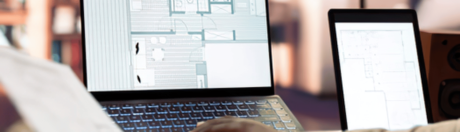
Floor plan digitization is the process of converting a physical or file-based building plan into an editable digital model that operational teams can use to manage rooms, desks, zones, and assets without requiring CAD software or architectural training.
A PDF floor plan in SharePoint gives teams something to look at. It stays static. Converting it into an editable digital model takes minutes with current tools, and any ops team member can run the conversion from the file already on hand. The input is a PDF, a CAD export, or an architect file. The output is a 2D and 3D model the whole team can edit, share, and connect to booking, facility, and access systems already running in the building. This guide walks through the digitization options, the steps involved, and what the resulting model makes possible for ops.
Key takeaways:
Most buildings have a floor plan document already. The starting file can be a PDF, a labelled image, or a CAD drawing, and the team sourcing it can work from whatever plan document they already have on file. Three file types work reliably as inputs for automated digitization.
PDF floor plans are the most common starting point. Building management companies, landlords, and facility teams hold PDF versions of floor plans from lease handovers, fit-out packages, or previous renovations. A PDF with visible room labels, corridor markings, and legible dimensions gives the digitization tool the information it needs to read the spatial structure and build a model from it.
CAD exports such as DXF or DWG files produce the cleanest input. If an architect or building surveyor has provided a digital drawing at any point during the building’s life, the exported version of that file carries precise dimensions and layer data. Teams often find these files in old project folders, handover packages, or property management archives. An older file works well for buildings where the overall layout has remained the same since the plan was drawn, and the team edits the resulting model afterward to reflect recent changes.
Labelled images work where PDFs or CAD exports are unavailable. A photograph of a printed floor plan, a screenshot of a drawing, or a scanned paper document works as a starting point, provided room labels and dimension markings are visible and legible. The output quality from labelled images tends to be lower than from clean PDF or CAD exports, and the team should expect to spend more time on manual editing after conversion.
What to check before uploading:
A plan file that meets these criteria is ready to digitize.
Automated digitization uses computer vision and AI to read the spatial structure of a plan file and render it as an editable digital model. The process runs inside the tool, requires no technical input from the team, and produces a result in approximately 40 seconds for a standard office floor.
The process follows three steps.
Step 1: Upload the plan file. The team uploads the PDF, CAD export, or labelled image to the digitization tool. HiSpatial accepts PDF files, CAD exports, and image files with visible room labels and dimension markings. Architect exports produce the most accurate results, and the team uploads one floor at a time for multi-floor buildings.
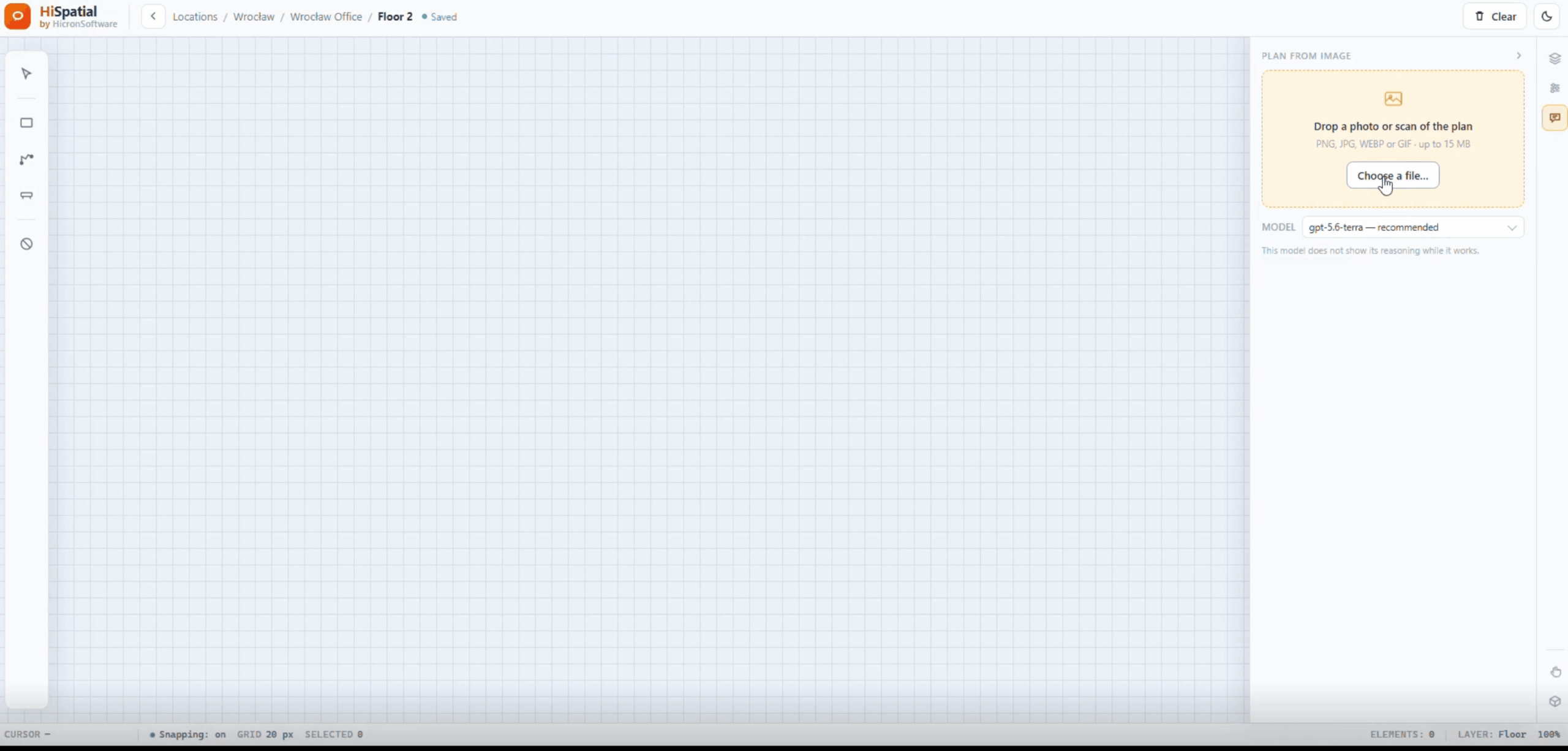
Step 2: The tool reads the plan and renders a model. The system identifies walls, corridors, rooms, and structural elements from the uploaded file. Room labels are read from the document and applied to the corresponding spaces in the model. The tool builds a 2D floor plan and a 3D model from the same source file. The result appears in the tool’s interface in approximately 40 seconds for a standard floor plan.
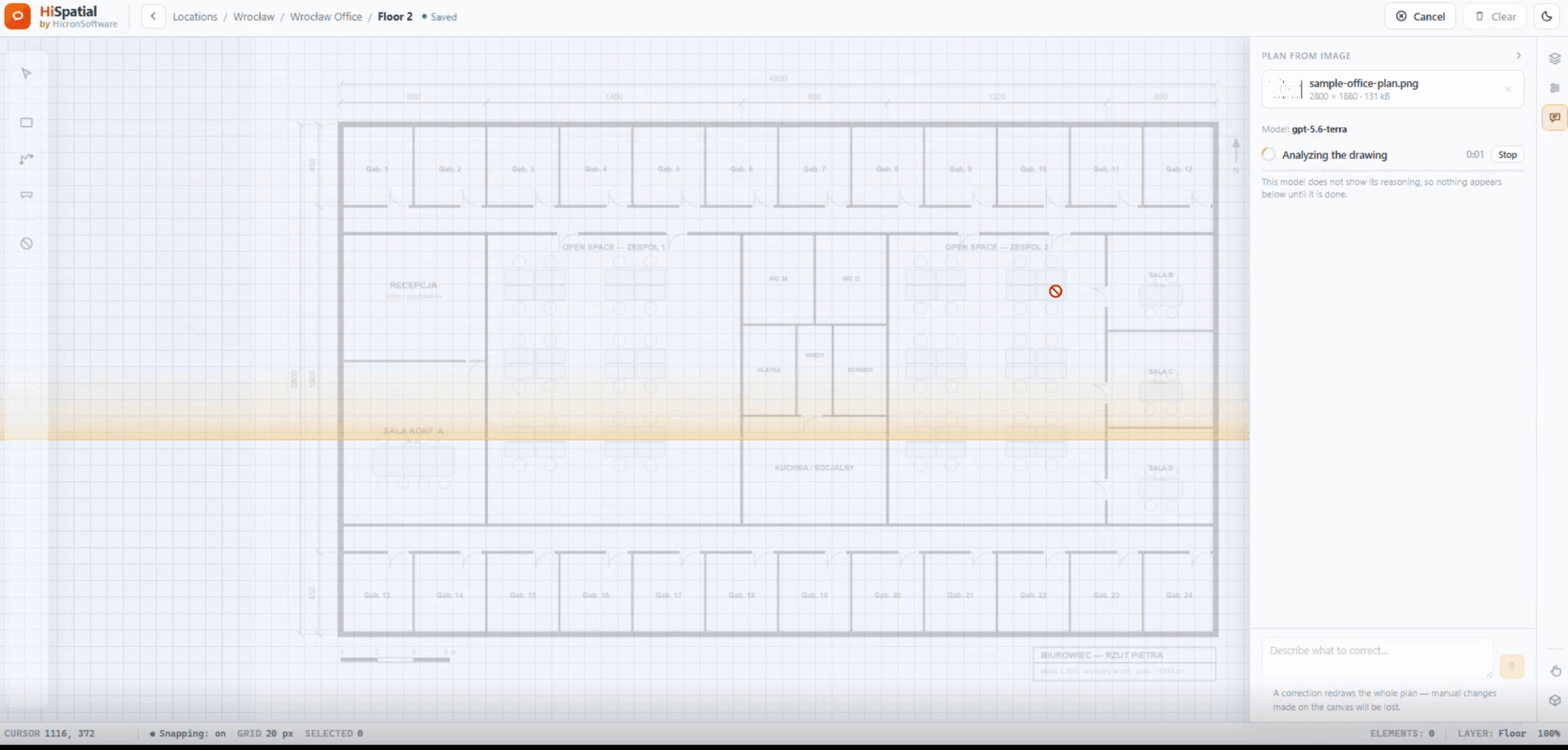
Step 3: The team reviews the rendered model. The 2D plan and the 3D model are available immediately after processing. The team navigates the model, checks that rooms are labelled correctly, and confirms that the spatial structure matches the building. Spaces that were labelled in the source file appear with their names applied. Unlabelled rooms appear as generic spaces ready for the team to name. The model is live and ready for editing at this point.
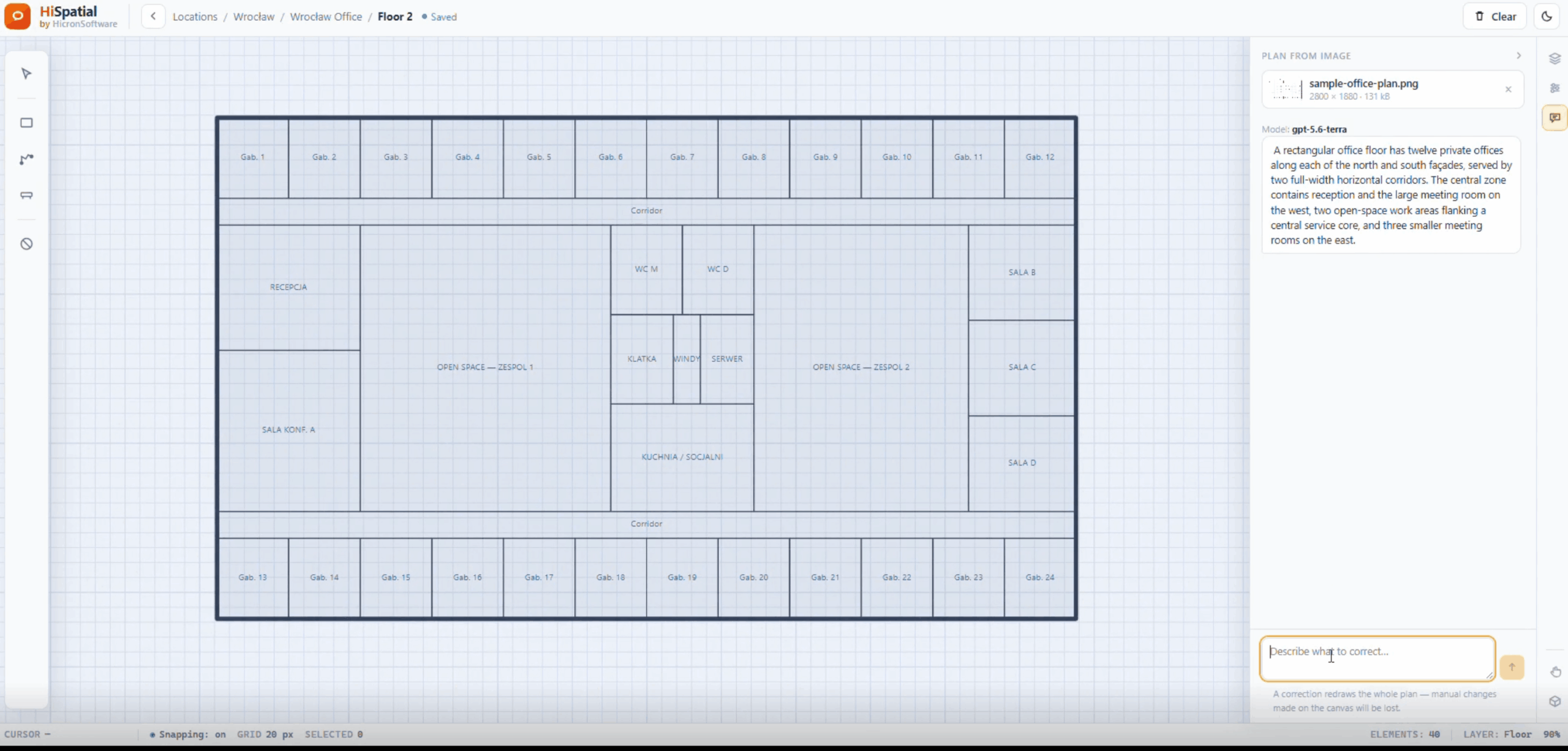
The quality of the output depends on the clarity of the input. A clean architect PDF with legible labels and consistent dimension markings produces a model that is ready to use with minimal adjustment. A scanned image of a worn paper plan produces a model that needs more editing to reach the same quality. The team’s time investment after conversion reflects the quality of the starting file rather than the complexity of the digitization process itself.
The digital model produced by automated digitization is editable from the moment it renders. Two editing modes are available, and the team uses whichever is faster for the change at hand.
AI chat editing lets the team describe changes in plain language. A team member types an instruction such as “rename room Server Room to Meeting B” or “add a desk cluster in the open area near the north corridor” and the system applies the change to the model. Chat editing is fast for renaming rooms, adjusting zone labels, and making layout changes that the team can describe in a sentence. The AI reads the model’s current state, applies the instruction, and shows the updated version immediately.
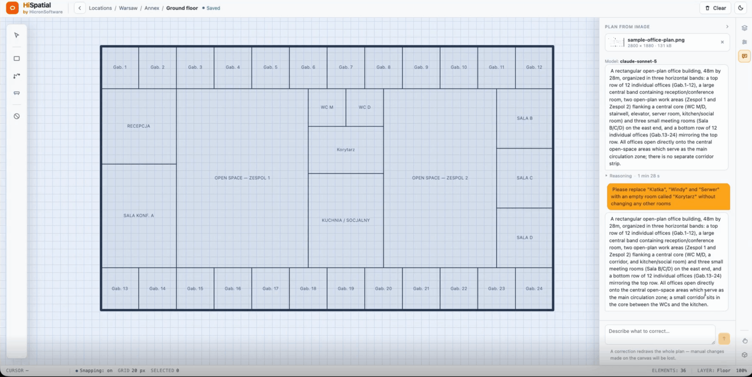
Manual editing by clicking on the plan lets the team work directly on the floor layout. The editing tools allow the team to place desks on specific locations, draw walls and partition lines, mark zones such as collaboration areas, storage rooms, and reception areas, remove spaces that were demolished in a recent renovation, and adjust room boundaries. Manual editing works well for precise spatial changes and for adding new elements that the AI chat would need a longer description to place accurately. The 2D and 3D views are linked, so a change made in the 2D editor appears in the 3D model immediately.
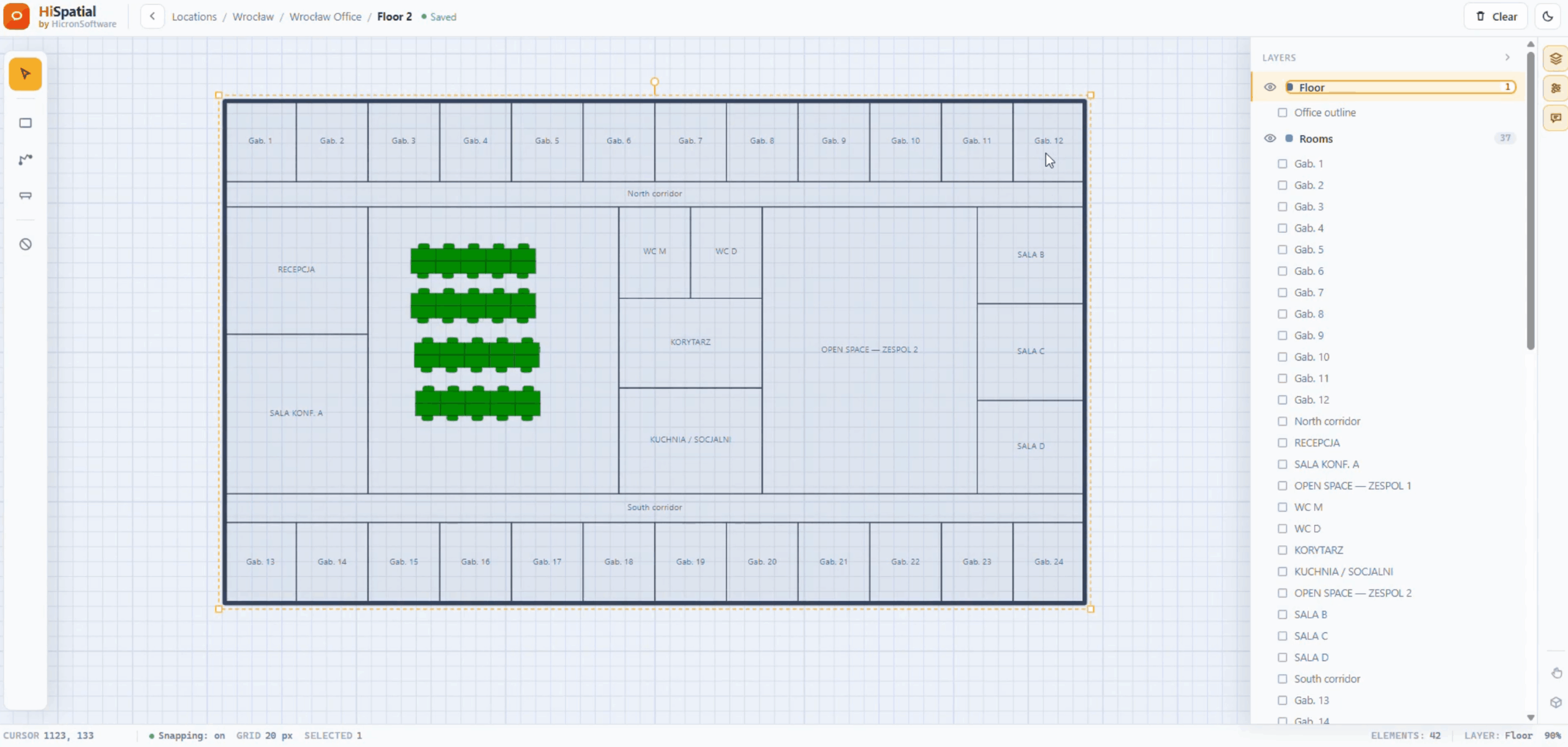
Both modes are available at the same time. A team managing a remodel might use the AI chat to rename every room on a floor and then switch to manual editing to adjust the desk layout in one zone. The switch between 2D and 3D happens at any point without saving or rebuilding the model.
Editing after a renovation or reconfiguration follows the same process. The team uploads the updated plan file, reviews the new model, and edits the sections that changed. For buildings where the structural layout changes infrequently and only furniture and zone assignments change regularly, the team typically edits the existing model directly rather than starting a new conversion.
Automated digitization covers the most common scenario: a team with an existing plan file and a need for a working digital model quickly. Other approaches exist for teams working under different constraints or inside specific platform environments.
|
Approach |
Input needed |
Time to first model |
Who does the work |
Model portability |
|
Automated digitization (HiSpatial) |
PDF, CAD export, or image |
~40 seconds |
Ops team member |
Connects to booking, FM, access systems |
|
Manual draw inside booking platform |
Starting from scratch or reference image |
Hours per floor |
Whoever handles platform setup |
Inside the booking platform only |
|
CAD bureau outsourcing |
Existing drawings or site survey |
Days to weeks |
External specialist |
CAD file delivered; requires conversion for ops use |
|
Scan-to-CAD service |
Physical site visit |
Days to weeks |
External specialist |
CAD file; same portability constraint |
Manual drawing inside booking platforms such as Archie, OfficeRnD, or Nexudus lets operators build a floor plan directly inside the booking tool’s admin interface. The result is embedded in the booking experience without a separate tool to manage. The constraint is that manual drawing takes hours per floor and produces a model that stays inside the booking platform, with limited paths to external systems.
CAD bureau outsourcing works for organizations that need a precise architectural record and have the timeline to wait. A CAD specialist redrafts the floor plan from existing drawings or conducts a site survey and delivers a DXF or DWG file. That file then needs conversion into an operational model before it can connect to booking or facility tools. The process is accurate and produces a durable drawing record, yet the timeline and cost exceed what most ops teams need for a working floor plan.
Scan-to-CAD services make sense for buildings where no digital plan exists at all: older properties where only paper records remain, or sites where the original drawings were lost. A surveyor visits the site, measures and documents the space, and delivers a digital drawing. The output is a CAD file, which then follows the same conversion path as an outsourced CAD bureau delivery.
For most office teams that have a PDF or CAD export on hand, automated digitization covers the job faster and at lower cost than the alternatives.
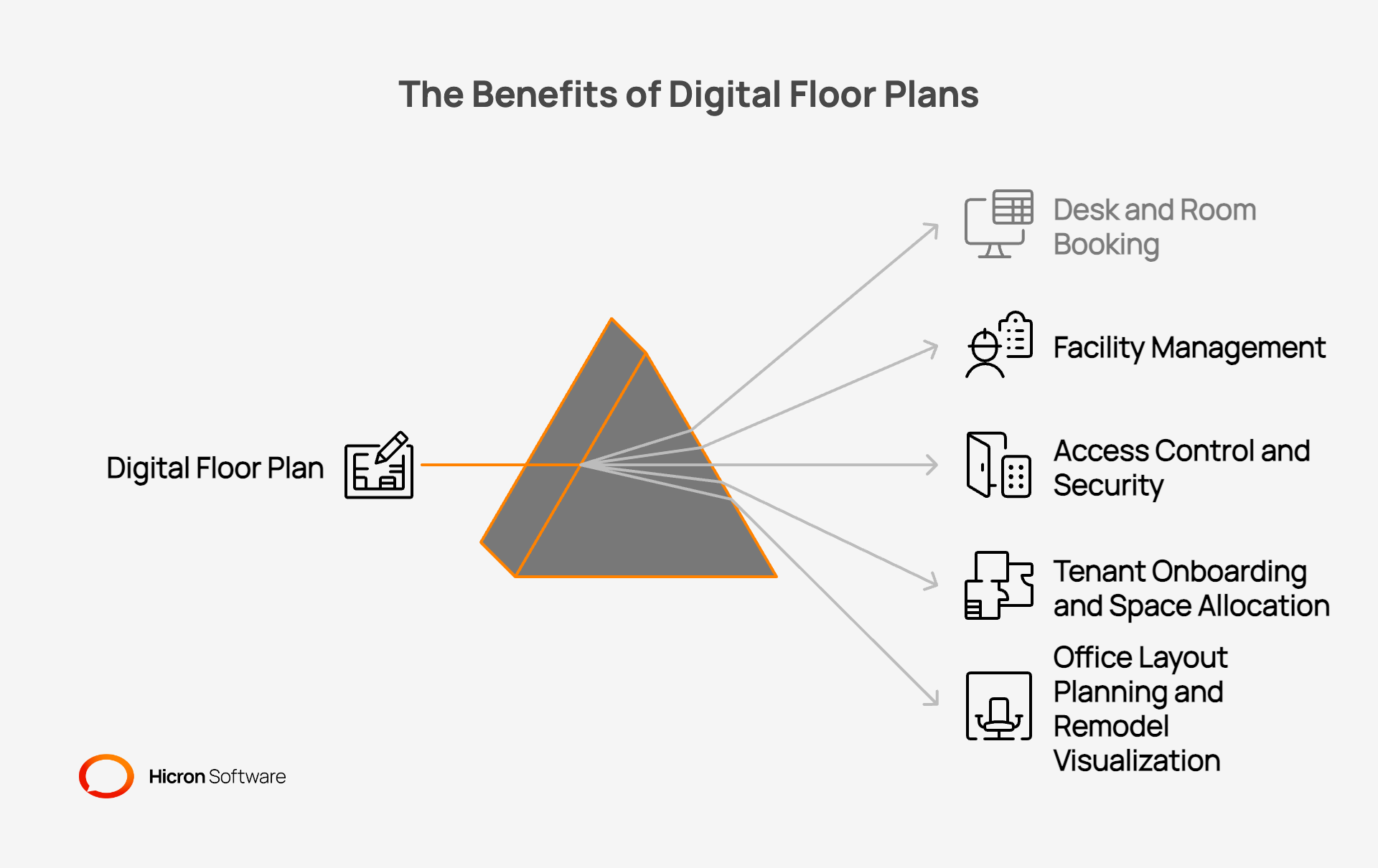
A working digital floor plan is a spatial foundation that other systems read from. The same model connects to multiple workflows without rebuilding for each one.
Desk and room booking. Booking systems display the floor plan as a visual desk picker. Staff select a desk by clicking its location on the map. The booking system reads the floor plan to show which desks are available and which are reserved. When the floor plan changes, the booking interface updates automatically. The booking system reads directly from the connected digital model to keep the desk picker current.
Facility management. Maintenance tasks pin to a physical location in the floor plan. A technician receiving a work order navigates to the correct room because the spatial reference is clear. Asset registers tie equipment to the space it occupies. Inspection records reference the zone that was checked. The floor plan model provides the spatial layer that turns work order text into a navigable location.
Access control and security. Access zones in the floor plan map to door controllers, reader groups, and routing rules in the access control system. When a zone is added or reconfigured, the access control system reads the updated spatial data rather than requiring manual re-entry of zone boundaries.
Tenant onboarding and space allocation. Property managers assign tenants to specific floors and zones by reference to the digital model. Onboarding packets include a visual plan of the tenant’s space. Renovation and fit-out planning runs from the same model, with the team visualizing changes before construction begins.
Office layout planning and remodel visualization. The 3D model lets teams compare layout options on screen before anything moves on site. A planned remodel appears in the model first. The team reviews it, adjusts zones and desk clusters, and confirms the layout before briefing contractors.
See your own floor plan as a working digital model.
HiSpatial converts an existing PDF or CAD export into an editable 2D and 3D floor plan model. The process takes approximately 40 seconds for a standard office floor. The resulting model is ready to edit by clicking on the plan or typing plain language instructions, and it connects to the booking, facility, and access systems the team already runs.

The fastest approach is uploading an existing PDF or CAD export to an automated digitization tool such as HiSpatial. The tool reads the plan file, identifies walls, corridors, and room labels, and renders a 2D and 3D model in approximately 40 seconds. The ops team reviews the result and edits it directly without specialist training. This approach works for any team that has an existing plan file, which covers most commercial offices built or renovated in the past thirty years.
A digital floor plan connects to desk and room booking systems, facility management platforms, access control systems, and tenant onboarding workflows. Booking systems read the model to display a visual desk picker. Facility platforms use the spatial layer to pin work orders and asset records to physical locations. Access control systems map door controllers and reader groups to zones in the floor plan. Tenant management tools reference the spatial model during space allocation and onboarding. The floor plan becomes the shared spatial reference that each system reads from rather than maintaining its own separate data.
Automated digitization tools work from existing plan files and produce an editable digital model without the team touching CAD software at any point. Ops teams edit the resulting model by clicking on the plan or typing instructions in plain language. CAD software such as AutoCAD or Revit is used by architects and engineers to document buildings during design and construction. Operational teams working from existing buildings manage layouts and zones inside the digitization tool rather than in CAD.
Automated digitization tools such as HiSpatial process a standard office floor plan in approximately 40 seconds from the moment the file uploads. The team adds editing time on top of that: a floor plan that matches the current building layout closely may need fifteen to thirty minutes of review and adjustment. A floor with many changes since the last document update takes longer. CAD bureau outsourcing takes days to weeks depending on the scope and the bureau’s queue.
A PDF floor plan is the most common input for automated digitization. Clean PDFs with visible room labels, corridor markings, and legible dimensions work well and produce accurate models. Scanned PDFs of printed drawings also work, with results that may need more manual editing after conversion to match the quality produced by a clean digital PDF. Architect exports from design software produce the most accurate and complete models.
Hicron Software proved to be a trusted partner with unmatched technical expertise, delivering a scalable and user-friendly web application that was pivotal to our successful U.S. market expansion.

Hicron’s contributions have been vital in making our product ready for commercialization. Their commitment to excellence, innovative solutions, and flexible approach were key factors in our successful collaboration.
I wholeheartedly recommend Hicron to any organization seeking a strategic long-term partnership, reliable and skilled partner for their technological needs.

After carefully evaluating suppliers, we decided to try a new approach and start working with a near-shore software house. Cooperation with Hicron Software House was something different, and it turned out to be a great success that brought added value to our company.
With HICRON’s creative ideas and fresh perspective, we reached a new level of our core platform and achieved our business goals.
Many thanks for what you did so far; we are looking forward to more in future!

Hicron is a partner who has provided excellent software development services. Their talented software engineers have a strong focus on collaboration and quality. They have helped us in achieving our goals across our cloud platforms at a good pace, without compromising on the quality of our services. Our partnership is professional and solution-focused!

The IT system supporting the work of retail outlets is the foundation of our business. The ability to optimize and adapt it to the needs of all entities in the PSA Group is of strategic importance and we consider it a step into the future. This project is a huge challenge: not only for us in terms of organization, but also for our partners – including Hicron – in terms of adapting the system to the needs and business models of PSA. Cooperation with Hicron consultants, taking into account their competences in the field of programming and processes specific to the automotive sector, gave us many reasons to be satisfied.